

By Dave Roberts and Glyn Davis
The main purpose of these articles is to pass on our experiences to other members who feel that they may have a lack experience in any particular area. We hope that you can benefit from these articles.
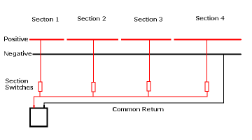
Let’s start with the original layout as it was some two years ago. The original layout was wired using what is known as the ‘Common Return’ system of wiring.
That is to say, ALL of the ‘FEEDS’ went to the layout via an ON/OFF switch and ALL of the ‘RETURNS’ were joined together to form the ‘Common Return’. Thus, we get its name.
The wire used was ex GPO single strand wire. It was many years old and had been broken in many, many places, caused mainly by ‘Age Hardening’ of the wire itself. With age copper hardens and can break very easily. The normal cure is to heat up the copper to soften it again. This is not practicable.
These breaks had been the subject of many ‘Quick Fixes’ over a prolonged period of time and any original ‘Colour Coding’ System had deteriorated into something along the lines of “Use anything just to get it going again”. Sound familiar to anyone?
The end result was a layout that was electrically one huge mess that no longer worked. Worse still, nobody could remember how it was originally wired.
Given this position, it was decided, after much debate, that the easiest and quickest solution would be to rip out all of the old wiring and to re-wire the entire layout using new, multi-stranded wire.
At the same time as rewiring the layout it was also decided that we should address some basic flaws in the original design of the layout plan to make it easier to operate and to utilise the limited space available to us upstairs more efficiently.
This involved:
Re-aligning the Main Station which was then sprawled diagonally across the room.
Adding some ‘Reception Sidings’ to the Low Level and
Moving the Upper Level Station and to incorporate a link to the ‘009 Room’.
These additions and alterations led in turn to two other major changes having to be made:
The design and making of three new Control Panels for the layout and
The making of a raised floor section at the Main Station so that the operators ould see around the layout more easily.
Splitting the Layout
The new layout breaks down quite easily into several self-contained sections. Each one is powered by its own separate power supply. We call these sections ‘POWER DISTRICTS’.
These are:
Upper Level UP Main Line (Clockwise)
Upper Level DOWN Main Line (Anti-Clockwise)
Low Level UP Main Line (Clockwise)
Low Lever DOWN Main Line (Anti-Clockwise)
Main Station, Sidings and Shed (Inbound)
Main Station, Sidings and Shed (Outbound)
009 Branch and Sidings
This breakdown into ‘POWER DISTRICTS’ allows us to run 7 separate trains, independently, at the same time.
However, these ‘Power Districts’ are far too big for the operator to have full view of the train at all times and the power draw on the transformers would be too much for just the one ‘FEED’ and ‘RETURN’ to cope with.
Also, we do need to stop one train and substitute it for another or else we would get bored very quickly just running round and round all of the time, wouldn’t we?
Track Sections
To overcome the power supply problem and give the operator some leeway to ‘play’ within each Power District they have been broken down into several smaller and more manageable ‘TRACK SECTIONS’.
Each ‘Track Section’ is completely electrically isolated from its adjacent neighbour. Both the ‘FEED’ and ‘RETURN’ are switchable - they are fed to the rails via a DPDT switch.
The Upper Level UP Main Line (Clockwise) is broken down into the following ‘Track Sections’:
Upper Station Platform Loop
Upper Station Through Line
Upper Station 009 Bay/Branch/Sidings
The Reverse Loop
Main Line Upper Station Approach
Main Line Upper Station Departure
Main Line Reverse Loop Approach
Low Level to Upper Level Loop
The Upper Level DOWN Main Line (Anti-Clockwise) is broken down into the following ‘Track Sections’:
Upper Station Platform Loop
Upper Station Through Line
009 Bay/Branch/Sidings (Changeover Section)
Main Line Upper Station Approach
Main Line Upper Station Departure
Upper Level to Low Level Loop (Changeover Section).
The Lower Level UP Main Line (Clockwise) is broken down into the following ‘Track Sections’:
Passing Loop
Through Line
Main Line Approach
Main Line Departure
Low Level to Upper Level Approach (Changeover Section)
Main Station Departure (Changeover Section)
The Lower Level DOWN Main Line (Anti-Clockwise) is broken down into the following ‘Track Sections’:
Outer Passing Loop
Inner Passing Loop
Through Line
Main Line Departure
Main Line Approach
Reception Sidings/Headshunt
Main Station Approach (Changeover Section)
Upper Level to Low Level Loop (Changeover Section)
The Main Station is treated differently so as to permit shunting and locomotive changing to take place. The Main Station breaks down into three main areas:
The Platform Lines
The Sidings and Yards
The Engine Shed
The idea here is to allow two operators to control any train movements within the confines of the Main Station. How these are split down is a matter for the two operators to agree but suffice it to say that the logical split would be that an ‘Inbound’ passenger train would go to the platforms and the ‘Inbound’ Freight train would go to the yards.
The shed ‘Pilot’ would place a relief locomotive at the other end of the passenger train to take it back out of the station or shunt the wagons in the yard. The incoming locomotive would then be released to go onto the shed for coaling, watering and turnaround on the turntable in preparation for its next duty.
The Main Station is broken down into the following ‘Track Sections’:
Main Coach Storage Line (1)
Platform 1
Platform 2
Platform 3
Platform 4
Platform 5
Bay
Yard Siding 1
Yard Siding 2
Yard Siding 3
Yard Siding 4
Coal Stage Upper Level
Coaling Stage Lower Level
Water Road
Shed Road 1
Shed Road 2
Storage Road 1
Storage Road 2
Headshunt
Turntable Approach
Turntable
The end of every platform line and yard siding is electrically isolated to hold the ‘incoming’ locomotive once uncoupled from its train whilst the station ‘pilot’ removes the rolling stock.
The ‘Changeover’ Sections
There are five ‘Changeover Sections’ on the layout. These are strategically placed so as to allow trains to be passed from one controller to another.
With one exception all of these Changeover Sections are powered through a Push Button type switch. This is to ensure that the Controller taking over the train cannot leave the Changeover Section powered and thereby risk a possible collision.
If we start from the Main Station the Changeover Sections are:
Main Station ‘Outbound’
Lower Lever to Upper Level Loop
Upper Level Reverse Loop
Upper Level to Lower Level Loop
Main Station ‘Inbound’
The ‘Outbound’ train is held at the signals, on the Changeover Section, to await access to the Lower Level UP Main Line. The Changeover Section can only be powered / controlled by the Lower Level UP Main Line Operator from that Control Panel.
When a train is to be passed to the Upper Level it has to climb up a steep gradient. The Upper Level UP Main Line Operator has control over the whole loop from the access point on the Lower Level to the Upper Level UP Main Line. This Changeover Section is powered / controlled by a switch on the Upper Level Control Panel and can only be powered / controlled by the Upper Level UP Main Line Operator.
When the Lower Level UP Main Line Operator ‘Reverses’ the access point the Operator only has control of any train as far as the point itself. The train will be held there, blocking the UP Main Line, until the Upper Level UP Main Line Operator is ready to accept the train.
The Upper Level Reverse Loop has a Changeover Section. The Upper Level UP Main Line Operator can drive a train onto the Reverse Loop as far as the Changeover Section situated at its access point onto the Upper Lever DOWN Main Line. The Changeover Section can only be powered/controlled by the Upper Level DOWN Main Line Operator when the Operator is ready to accept the train onto the Upper Level DOWN Main Line.
When the Upper Level DOWN Main Line Operator ‘Reverses’ the access point the Operator only has control of any train as far as the Changeover Section. The train will be held there, blocking the DOWN Loop, until the Lower Level DOWN Main Line Operator is ready to accept the train.
The Changeover Section can only be powered / controlled by the Lower Level DOWN Main Line Operator from that Control Panel.
When ready to accept the train the Lower Level DOWN Main Line Operator ‘Reverses’ the access point and pushes the button to move the train onto the Lower Level DOWN Main Line.
When the Lower Level DOWN Mail Line Operator decides to send a train into the Main Station the access point is ‘Reversed’ and the train proceeds onto the ‘Approach Line.
The ‘Inbound’ train is held at the signal before the turntable approach and waits there, on the Changeover Section, until one of the Main Station Operators is ready to receive it into the station. The Changeover Section can only be powered / controlled by either of the two Main Station Operators.
When ready to accept the train into the Main Station the Main Station Operator ‘Reverses’ the access point and pushes the button to move the train into the appropriate part of the Main Station.
So, that’s how we did it. We now have a layout that is readily broken down into separate, independent, electrical ‘Power Districts’. These ‘Power Districts’ are further broken down into ‘Track Sections’ and each of these ‘Track Section’ is controlled by a Hand Held Controller.