

Introduction
The following is a useful reference for those less familiar with electricity and electrical matters.
These `rules’ are common to all layout wiring, whether DC or DCC.
These ‘rules’ apply to each `CAB’ or `Power District’.
A ‘CAB’ is a term used to describe the hand controller used to control a locomotive. The operator is supposed to be in the ‘CAB’ of the locomotive that they are controlling – thus the name.
A `Power District’ is that part of a layout controlled and supplied by a single Command Station or Controller.
DO NOT MIX WIRING BETWEEN `CABS’ OR `POWER DISTRICTS’, EXCEPT IN THE MANNER STATED BELOW.
NUMBER RULE
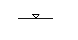
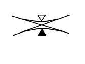
1 Take each FEED INDEPENDANTLY to the layout. Usually via an `ON/OFF’ switch.
If you number the feeds you can write it inside or alongside the small triangle
SYMBOL
NUMBER RULE
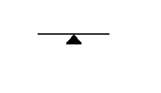
2 Join ALL RETURNS together. This is often known as ‘COMMON RETURN’ wiring when
using DC.
SYMBOL
NUMBER RULE
3 NEVER allow `Feed’ and `Return’ to touch. This creates a ‘Short Circuit’.
One of the biggest problems to be avoided with any layout is the `short circuit’, primarily caused by de-railment of locomotives or rolling stock that can bring the entire layout to a sudden halt. This can be very embarrassing, especially so if you just happen to be exhibiting the layout.
NUMBER RULE
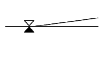
4 ALWAYS feed current to the TOE end of a point.
The term ‘Common Leg’ is becoming more used today since both diverging rails come from the same, ‘common’ source.
SYMBOL
NUMBER RULE
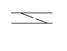
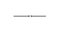
5 ALWAYS have a `DOUBLE BREAK’ where points are laid`Back-to-Back’.
The break is in BOTH rails and can be achieved easily either by placing INSULATE fishplates on each rail or simply by cutting the rails with a saw.
SYMBOL
NUMBER RULE
6 There should always be a `DOUBLE BREAK’ on any CONTINUOUS run.
The reason for this is to break up long stretches of track into smaller, more manageable ‘Sections’.
SYMBOL
NUMBER RULE
7 A `DOUBLE-SLIP’ is ALWAYS a `Feed’ point.
You will need to isolate each of the four routes coming off of the slip.
SYMBOL
NUMBER RULE
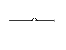
8 An `ISOLATED SECTION’ should be provided wherever a locomotive has to stand.
Normally found at the ends of platforms and reception sidings.
SYMBOL
NUMBER RULE
9 It MUST ALWAYS be possible to ISOLATE a train POSITIVELY against a `STOP’ signal.
These are often referred to as ‘Changeover’ Sections and protect one section from
another. e.g. The ‘UP’ Main Line from the ‘DOWN’ Main Line.
NUMBER RULE
10 It should be possible to isolate EVERY section of track, even though the controller is
energised. That is to say EVERY `FEED’ MUST BE SWITCHABLE.
NUMBER RULE
11 Keep ALL wires neatly `CABLED’ or enclosed in a cable duct.
NUMBER RULE
12 ALWAYS keep wiring as simple as you can to achieve the desired effect.
NUMBER RULE
13 NEVER let a `Section Break’ coincide with a baseboard join. With DCC, we challenge this
rule because each Board Section can be used as a ‘Sub-Section’.
NUMBER RULE
14 `Reverse Loops’ and ONE leg of a`Triangular’ Junction MUST be fed from a SEPARATE `REVERSE FEED’. – a D.P.D.T. Switch or Power Booster.
SYMBOL
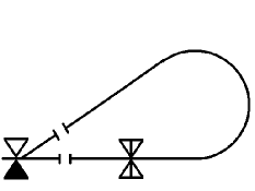
There are two possible variations of wiring these loops depending on whether or not you want to run your train ‘Out and ‘Back’ without stopping or not.
In the variant shown above you must stop the train whilst on the loop and reverse the current flow before you can get back to the station.
In the other variant the two feeds shown are reversed. While the train is on the loop all you need do is reverse the current flow at the common leg.
NUMBER RULE
15 When a locomotive is moving FORWARD with the controller set to the `Forward’ direction
then the RIGHT HAND rail – That is, the RH rail when viewed from the tender end looking forward – will be `POSITIVE’ in relation to the LEFT HAND rail.
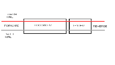
This is commonly known as the ‘Right Hand Rule.
Our guiding thought with most things that we do has always been:
“Keep it simple – Keep it stupid”
The simpler anything is then the easier it is to follow. Especially so when something goes wrong – and as we all know – it will go wrong!
It has been said by several DCC pundits that one of the greatest advantages of any DCC layout over a DC layout is `simplified’ wiring. Fine say I . . .
We have spent many, many hours under the boards, soldering iron in hand, trying to track down faults in circuits. Even with an up-to-date ‘Wiring Book’ it can be a nightmare – all those miles of coloured wires, cabled together.
What about those `Emergency Running Repairs’ – not written down or documented in any way –
“Just get it fixed so we can get the layout operating for the people.”
Hey-Ho . . . sounds familiar to anyone?