

The Basic Concepts
A layout can contain miles – yes MILES - of fine wire to power each section, the point and signal motors, relays, interlocks and the like.
You really do need a `Wiring Book’ to find your way around when a fault occurs. This is especially true if you did not have a hand in wiring the original layout.
Also, layouts expand or are changed to suit the particular whims of the operators and this will usually mean a change to or an addition to the wiring schema.
IF THERE IS NOWHERE TO NOTE THESE CHANGES DOWN THEN YOU LAY YOURSELF WIDE OPEN TO A NIGHTMARE SCENARIO.
When it comes to putting all of these ideas together to form our layout we need to consider the problems we may well encounter when wiring any layout.
Wiring Used on the Layout
Wiring runs are measured from the supplying Controller/Transformer to the Track Feed. Where this distance is over 10 metres – think of single 8ft x 4ft sections of board – then THICKER wires will be required to ensure that we do not get power loss over these longer distances.
We have tried to keep within these limits when re-designing the layout.
In a DC system, we tend to operate the locomotives at 0 – 12v DC utilising about 1A of current. The accessories use 15v AC or 12v DC.
In a DCC system, the power used is much higher. It utilises 16v AC and a MAXIMUM current of 5A.
This is because BOTH the power to operate the locomotives and all other accessories – point motors, signals etc. - and the power to transmit the `Command Signals’ around the track to the appropriate `DECODERS’ come from the same source.
Types of Wire
Electrical Wire comprised a metal core – usually copper, covered by an insulated outer covering – normally plastic. The core can be of two types:
A SOLID Core. This is not very flexible and is prone to break as it ages in use.
A MULTI-STRANDED Core. This is very flexible and is not prone to breaking.
ALL wiring used on the layout is MULTI-STRANDED for flexibility. Examples of each type of wire used on the layout are described in detail.
We have also used Copper Tape as a conductor within the Control Panels. This can carry up to 20 amps of current at 12 volts – more than sufficient to operate our point motors. It can also be used as the main power bus around the entire layout.
The wire itself has a resistance to the flow of electricity through it. The smaller the diameter of the wire the less current it can take without getting hot – sometimes very hot when a ‘short’ occurs – and then create a possible fire hazard.
Just who set the fire alarm off recently!
The table below shows some very useful data for the recommended wire sizes for any layout:
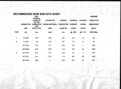
The table above shows the three types of wire that we use on the layout.
These are:
the first line – 7 x 0.2 - which we use for all Feeds to the track and points.
Had this been for a DCC Layout then the third line - 16 x 0.2 would have been used instead because of the higher current used.
the fourth line – 24 x 0.2 - is used within the control panels to carry the higher
current required to operate several point motors simultaneously.
the last line – 32 x 0.2 - that we use for both the Main Power Bus and the Accessory Power Bus around the entire layout to carry sufficient current to be able to operate all points
simultaneously, should the need ever arise – like little fingers throwing point switches when the power is off the system – the system reset.
So, we use larger diameter (32 x 0.2) wires – the ‘MAIN POWER BUS’ to get as much electricity out and away from the Transformer/Controllers as is possible and then use smaller diameter wires (7 x 0.2) that are easier to handle to make the actual connections to the track – the ‘FEEDER’ wires.
The larger wire is called Bus (Pronounced BUZZ – as in Bee). We have one pair of wires going all around the layout carrying the power to operate all of the points, simultaneously, if necessary!
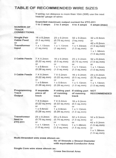
The following table details one manufacturers recommended Wire sizes to be used:
Obtaining and Maintaining a ‘Good Electrical Connection’
To achieve a reliable power supply to all parts of the layout is essential. To achieve this follow these simple guidelines:
ALL track joins SHOULD be `ELECTRICALLY BONDED’ to ensure that the power gets through the rails to the locomotives and accessories . . .
or, to put it another way. .
EVERY piece of rail should be SOLDERED to something.
That `something’ can be:
(1) Another piece of rail.
Soldering all of the `Rail Joiners’ (Fishplates) may seem like a good idea at first sight but you MUST consider the temperature variations that will be experienced by the track and the expansion and contraction that such variations of temperature will cause around the layout.
Also, there is sometimes the need to re-lay a section of track. If you have soldered the fishplates to a point, for example, then there will be a very high risk of damage to the pointwork and that can be very, very expensive!
Fitting `Expansion Joints’, just as in the prototype, may be one solution and some of these can be found on the layout. They look very neat!
Originally, we considered soldering only those joints that fall onto ONE Board Section and to use `Bridging Sections’ across the board sections to both protect the rail ends from damage when being moved and also to act as `Expansion Joints’ when necessary.
Again, a little more work would have been required but would the effect be worth all of the effort? However, since the upstairs layout is not intended to be a ‘Portable’ one, what’s the point?
(2) A piece of wire.
The `Wire’ can be either a `FEEDER’ wire, a `JUMPER’ or a ‘BOND’ from an adjacent rail (at the point).
A `JUMPER’ or a ‘BOND’ is simply a piece of wire that electrically bonds two pieces of equipment together. It should be of sufficient size to carry the maximum expected current load.
A ‘DROPPER’ or ‘FEEDER’ wire (Often referred to simply as the ‘TRACK FEED’) are the two pieces of wire that connect both rails to the main bus wires.