

The Pointwork
We now need to have a real close look at the point work used on the layout. As we mentioned earlier, ALL have been modified in such a way as to make them both ‘POWER ROUTED’ and ‘DCC FRIENDLY’.
A ‘POWER ROUTED’ point is one that is half way to being ‘DCC FRIENDLY’ in so far as the frog is powered through one of the spare relay switches fitted to the point motor such that the polarity is set to the same as the ‘ROUTE’ that has been set on the point. It sounds very complicated but when you study the diagrams shortly you’ll see exactly what we mean.
A ‘DCC FRIENDLY’ point is one that is already ‘POWER ROUTED’ and in addition is wired so as to reduce, if not entirely eliminate the possibility of causing a ‘Short Circuit’ when in use that would bring the whole layout to a halt in the worst case or cause a loss of power and signal strength through the rails.
The last series of diagrams in this part shows you just how to make any point both ‘POWER ROUTED’ and ‘DCC FRIENDLY’.
All of the views are as seen from below the board. You are looking at the underside of a RIGHT HAND point.
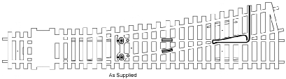
Fig 1 – The Point Motor ‘As Supplied’
Fig.1 shows you the point ‘As Supplied’ straight out of its box. The frog is pre-wired and READY to make it ‘POWER ROUTED’ but it is ready for immediate used.
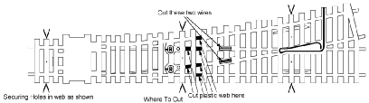
Fig 2 – The Point Motor Where to Cut
Fig.2 shows you the modifications that you need to make to the underside of the point.
Note the indicated positions of the pre-drilled fixing holes used to secure the point to the baseboard.
Here is what you do:
Firstly, cut the two wires indicated. These are called ‘BONDS’. Doing this will electrically isolate the frog rails from the rest of the point rails.
If you turn the point over and look carefully at the two rails that converge to form the frog you will notice a small piece of plastic insert in the rails. These ‘BONDS’ allow the electricity to ‘jump’ over these insulated sections and to feed the frog.
Secondly, cut away the plastic web of the point in each of the six positions indicated to reveal the underside of the metal rails below. These will be used to allow you to solder four additional new ‘BONDS’ to the rails at these positions.
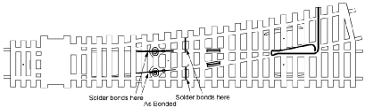
Fig 3 – The Point Motor ‘As Bonded’
Fig.3 above shows the additional, new bonds soldered in position.
These new ‘BONDS’ make the point ‘DCC FRIENDLY’ by electrically ‘Bonding’ both ‘Stock Rails’ to the adjacent ‘Closure Rails’ and defeat a possible ‘Hot Spot’.
Both of the mechanical pivots built into the point are a possible ‘Hot Spot’ and it is well worth the little additional work to bond over these pivot points to overcome this possibility.
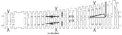
Fig 4 – The Point Motor ‘As Modified’
Fig.4 shows the underside of the point when modified but BEFORE we prepare it for ‘POWER ROUTING’.
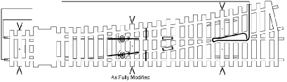
Fig 5 – The Point Motor ‘As Wired’
Fig.5 shows the additional wiring required to make the point ‘POWER ROUTED’.
A wire needs to be soldered to each rail at the ‘Toe’ end of the point of sufficient length so as to be able to be soldered to either of the spare switches on the point motor.
The Pre-Wired frog wire may or may not be long enough to reach back to the point motor. If not then solder a sufficient length of wire to the pre-fitted wire to be able to reach either of the two spare switches on the point motor.
The last four diagrams show how to wire both of the spare switches fitted to the point motor. It is up to you which one you choose or maybe one may get damaged and you will be forced to use the other.
Here is how to do it:
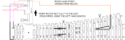
Fig 6 – Wiring the LH Point Motor Switch with the Point Motor set Fully to the LEFT
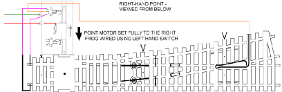
Fig 7 – Wiring the LH Point Motor Switch with the Point Motor set fully to the RIGHT
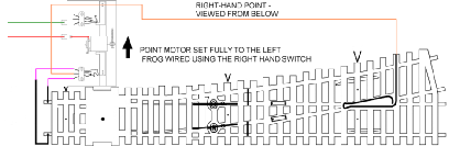
Fig 8 – Wiring the RH Point Motor Switch with the Point Motor set Fully to the LEFT
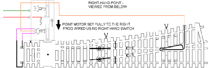
Fig 9 – Wiring the RH Point Motor Switch with the Point Motor set Fully to the RIGHT
It is a matter of personal preference whether or not you choose to solder the wires to the point motor switches first and then solder the other ends to the appropriate rail when fitted to the baseboard.
However, consider these points:
The switches are very small and contain small parts that are easily dislodged and lost.
The application of a hot soldering iron for too long will destroy the switch very quickly.
Work where it is easiest to get at what you are working on.
Gravity always works downwards.