

The Feed Switch
These are what are known as ‘DOUBLE POLE TRIPLE THROW’ (DPTT) switches or more commonly known as ‘Centre OFF’ switches. That is to say, the switch operates two separate circuits – the ‘FEED’ and the ‘RETURN’ – at the same time. It either ‘MAKES’ both circuits or it ‘BREAKS’ both circuits at the same time.
In this particular case they switch BOTH the ‘FEED’ and ‘RETURN’ circuits from the LEFT HAND Controller to a ‘CENTRE OFF’ position and then on to the RIGHT HAND Controller.
So, if a switch is set to the LEFT then the LEFT HAND Hand Controller has control of the ‘Track Section’ being supplied through that switch and when switched to the RIGHT then the RIGHT HAND Hand Controller has control of the ‘Track Section’ being supplied through that switch.
It now becomes a matter of ‘User Discipline’ to ensure that ALL Feed Switches are normally set to the CENTRE OFF position when not being used. Sounds simple but we’ll see!
Fig. 1 shows the wiring of a Feed Switch.
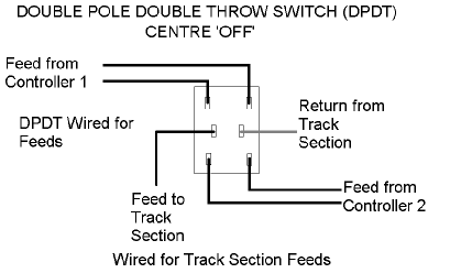
Fig 1 – Wiring of a DPDT Type Feed Switch
Some of the Feed Switches are of the ‘Push Button’ type and are wired such that the ‘Track Section’ fed by that Push Button is only energised whilst the button is being pushed. This type feed the ‘Changeover’ Track Sections between the different Control Panels
Fig. 2 shows the wiring of a ‘Push Button’ Type of Feed Switch.
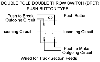
Fig 2 – Wiring of a Push Button Type Feed Switch
The Pointwork
The power to operate all of the point motors around the layout comes from a separate transformer that is capable of supplying up to 20 amps of current at 12 volts DC. This is quite sufficient to WELD metal to metal in the event of a ‘Short Circuit’! Therefore, we need to look at ways of reducing, if not totally eliminating, any possibility of a ‘Short Circuit’ ever occurring on the layout.
The Point Motor Switch
The Point Motor Switch is also a DPDT Type switch but it is NOT the ‘Centre ‘OFF’ type. It is simply switched from one side to the other to supply power to operate the ‘FULGAREX’ point motors used on the layout.
Fig. 3 shows the wiring of a DPDT when used to power point motors. The easiest way to identify these switches is by the crossover of the ‘FEED’ and ‘RETURN’ wires between the diagonally opposite terminals on the switch. These are well insulated from each other so as not to cause a ‘Short Circuit’.
All these switches do is to REVERSE the polarity of the supply being fed to the point motor so as to reverse its direction of movement.
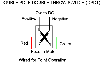
Fig 3 – Wiring of a Point Motor Switch