“Who Controls the Layout?”
Now we get to grips with the problems encountered when having to decide just who is actually controlling the layout and that opens up a whole new can of worms for us to get to grips with.
THE CONTROL PANEL – ‘REAL’ or ‘VIRTUAL’?
The use of the `Control Panel’ – ‘Central’, `Main’ or `Local’ - may not be required or regarded as essential when considering DCC but with DC they cannot be avoided.
These require Indicators, switches, relays etc all of which require wiring and this can be a nightmare for the uninitiated or non-technical person so can we really do without them?
Wiring is reckoned to be the second most time consuming aspect of building your layout and more often than not it is the cost savings of not having to use such items that is used as the argument to offset the higher cost of using DCC.
Both the Point and Signal `Address Codes’ or ‘Numbers’ can be displayed either directly on the layout board, adjacent to the relevant accessory or be put up onto a large `Signal Box Diagram’ for all operators to see; it’s really a matter of personal choice.
Computer programmes have been written to display this same information on a display – sometime referred to as a ‘Glass Panel’ but now more commonly referred to as a ‘Virtual Panel’.
However, consider this:
Currently, it is the `Operator’ who sets the `Route’ that they wish to take.
When more than one operator is working at the same time then, eventually, two operators are both going to want to use the same section of track . . . and now we have a problem . . . WHO IS IN CONTROL OF THE ROUTE? or to put it another way . . . .
Who has the `Controlling Authority’?
A serious conflict of interest arises here. More especially so when all we really want to do is to enjoy ourselves – so let us NOT lose sight of that simple fact, please.
In prototypical operation, the Signal Operator in the Signal Box determines which locomotives/trains have the ‘Right-Away’ (the ‘right-of-way’) over the ‘Block Section’ controlled by that Box.
We now want to look at the problems involved from both viewpoints and this article will, hopefully, be treated as a `Discussion Document’ by all of those directly concerned with this exciting, new, developments including the use of computers to help with the running of larger layouts when you are short handed.
PROTOTYPE SIGNAL CONTROL SYSTEMS
`Running Lines’, to use the correct term for our track layout, are divided up, for `Signalling’ and `Control’ purposes, into `Block Sections’, almost invariably with each `Section’ having a `Controlling’ Signal Box at EACH end.
It was a FUNDAMENTAL RULE of railway operation that in the NORMAL course of events, the objective was that only ONE train would be allowed to occupy a `Block Section’ at any one time and therefore a system of control, known as `ABSOLUTE BLOCK SIGNALLING’, was designed to achieve this objective.
In order to affect proper `Control’, each Signal Box had to be able, by use of its signals, to slow down and if necessary, to halt the progress of ANY train within the Block Section it controlled.
The diagram below shows a `Block Section’, with its TWO Controlling Signal Boxes, `A’ and `B’. Entry into the Block Section - from the LEFT HAND SIDE – was controlled by a `Starting’ signal, controlled by Signal Box `A’.
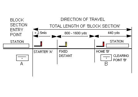
However, AUTHORISATION to lower this signal and therefore to let the train enter the `Block Section’ had to be obtained from Signal Box `B’ who would have first confirmed that the Block Section was not `Occupied’ by another train.
The other end of the Block Section – the RIGHT END SIDE – was defined by what was termed the `Clearing Point’ which lay 440 yards beyond (in advance of) Signal Box `B’s’ `Home’ signal.
If there was ANY part of a train anywhere between the `Clearing Point’ and Signal Box `A’s’ `Starting’ signal, the Block Section was deemed to be `OCCUPIED’.
This system of ‘Block’ working was the standard method of controlling the movement of trains and applied to the Main lines and Branch lines alike.
Most of the short branch lines in which there was just a junction and a terminus would constitute a single `Block Section’ so working such a branch line was fairly simple.
On longer lines with several junctions, the number of `Block Sections’ would multiply and then it was the Signaller who would have to use the `Block Instruments’ to pass trains along the line, Signal Box to Signal Box.
This system of working provided considerable safety but for single line working, there had to be methods of control to prevent not just collision from the rear but also head-on confrontations.
To prevent such an eventuality, a form of `Staff’ or `Token’ system was adopted. NO TRAIN COULD ENTER ONTO THE BRANCH WITHOUT POSSESSION OF IT.
In other words:
When operating any layout, whether using DCC or not, some form of `Control’ over its operation – train movements - is essential.
In the past, we have devised and used complex `Block Control’ systems and passed control from one operator to the next down the line until the train reached its destination. In such systems, the operator acted as both Operator and Signaller and thereby `Authorised’ any movement within the block under their direct control.
A rigid control system was forced upon all operators and train movements had to be choreographed with little or no room for individuals – until there was a breakdown or a de-railment and then the fun started!
In short, we all ended up running to the ‘Timetable’.
However, the operator can control the train along its entire journey which will cross several Block Sections, each requiring `Authority to Pass’ – the `Right-of-Way’.
The advent of DCC brought us a freedom of movement for every operator but as layouts grow, we now have to pay the price for such freedom.
Yes, you can move your train freely about but ONLY WITHIN THE BLOCK YOU CURRENTLY OCCUPY.
Can we improve on this state of affairs, somehow? We believe that we can.
Let us have a closer look at exactly what it is that we have at the moment, where we want to get to and use prototype working to hopefully, find our answers.
The mind boggles at just what confusion several, independent, train movements can cause
We know that the layout can be divided up into `Power Districts’, `Sub-Districts’, `Track Sections’ and ‘Blocks’. Let us see how this breakdown can be used to help us:
Power Districts - These can be the Main Stations.
Sub-Districts – These can be the Intermediate smaller Stations or even smaller parts of the bigger Terminus or Main Stations. For example the Up Platform Lines and the DOWN Platform Lines
Track Sections - These can be the sidings or loops.
Blocks – These can be the individual sidings or loops within the stations.
If we now apply the `Block Signalling Section’ method of CONTROL of the entire layout over the top of the ‘Power Districts’ idea then we can see that every station, large or small, can have many signal boxes – at least two. It is these boxes that should control entry to and exit from the Block Section and all sidings and loops within the block – at that station.
Now, do you remember the purpose of all of this? – we want to ENJOY OURSELVES running our model railway rather than getting bogged down by too many `controls’.
CONTROLLING ROUTE SETTING
So how can we accommodate both?
We can create a control system that enables the Signaller to control the movement of trains within the Block and from box to box but would the actual train operator get any satisfaction from this arrangement?
We very much doubt it.
So, here we have the nub of the problem.
How do we apply control yet make it `invisible’ to the operator?
One possible solution is `Route Mapping’ – a series of pre-defined ‘Routes’ from Box to Box from any given Departure Point to any given Destination together with the `Authorised Right-of-Way’ given to a SELECTED Train operator – The good old Timetable!
Before the purists amongst you start jumping up and down at this last statement let us toss this pebble into the pool . . .
A ‘ROUTE’, within the context of a ‘Signalling’ system, is defined as the path from one signal – the ENTRY Signal - to the NEXT SIGNAL – the EXIT Signal – along the chosen path. It is NOT from Departure Point to Destination. A ‘ROUTE IDENTIFICATION’ is normally named after the ENTRY Signal and not the entry point.
However, ‘Clearing’ the line for the express train operator will not suit the branch local goods train operator who just wants to carry on shunting in the yards without affecting the main running lines.
We need a modified form of control - `Route Control Operator Selection’ - that will permit both operators to use different parts of the same block at the same time provided that there is no risk of collision.
Perhaps our `Route Mapping’ should allow partial control of the smaller ‘Track Sections’ rather than absolute control of the whole block. For example, say we have control over those points and signals that only affect the Departure Platform or Siding, the main running lines through the intermediate stations and the Arrival Platform or Sidings at the destination.
What are the implications of all of this when we consider the `Route Setting’ requirements of the Train Operator on the one hand and the `Absolute Block Signalling’ requirements of the Signaller or Block Section Operator / Controller on the other?
REMEMBER – we are looking for a `WORKABLE’ compromise that is digitally possible to achieve.
The Train Operator would like:
To set the route ONCE – all the way from the `Departure Point’ to the `Destination Point’ – stopping at the intermediate stations on the route to take on and drop off passengers.
The Train Operator may or may not want to use any of the yards or sidings along the route or just the main running line through the platform.
This requirement is feasible and achievable, digitally – the control of the Main Line points and signals only – especially so where we have some `Double Track’ working.
`Single Track Working’ is an entirely different ball game and WILL REQUIRE some form of ABSOLUTE Control.
There are `Main Stations’ along the route where other train movements should not be hindered, especially so where we have separate `Up’ and `Down’ running lines and the movements do NOT affect any Main Running Line working.
Block-to-Block – Absolute Control
So, let us now have a look at the `Block-to-Block’ idea.
Currently, we can have a MAXIMUM of 7 Train Operators. ALL of them are capable of operating at the same time.
If we allow:
The priority `Express’ Train Operator to set the`remote’ route just prior to its departure.
The `Local’ Train Operator at any of the intermediate stations (`Block Sections’)
along that chosen path to temporarily override these`remote’ settings within their Local Block Section’.
Then, we will require some method of `storing’ the `remote’ express route settings as the `default’ setting for that particular block of all the points and signals that control the Main Running Lines through each section.
This now brings us back to the problem of BLOCK OCCUPANCY. . .
Which locomotive / train is currently occupying the block and more importantly, who has control of it?
The ‘Local’ Operator will have ABSOLUTE CONTROL over the ‘Local’ Block and MUST ensure that the main line is ‘Cleared’ for the express train to pass. Only when this is so will the default ‘remote’ settings be ‘enabled’ for the express to pass through the section safely and unhindered.
Similarly, we would also require that these `remote’ route settings be automatically CANCELLED when the express train passes out of each section. This implies some form of FEEDBACK from every train as it passes along its route.
Such `Routes’ can only be `SET’ whilst in `ACTIVE’ (current) memory, just prior to departure – using a `first in first out’ type of storage system with a facility to cancel any movement in the sequence and move the remaining planned movements up the chain.
You should also be able to re-insert a cancelled movement and move the rest, accordingly and to insert a NEW movement, as required. This would then allow the `Breakdown Train’ access to the system as the next authorised movement.
A list of all such `pre-programmed’ movements (Route Mapping) can be stored in `Backup’ memory, just like a timetable but they can be pulled out in ANY order that we choose.
It is vital that `Absolute Block Control’ be maintained if we are to avoid crashes. This, therefore, means that ANY `Route’ CAN ONLY BE RE-SET FROM THE `LOCAL’ CONTROL PANEL.
The `Re-set’ can only be done when the `Train Operator’ AT THE `LOCAL’ CONTROL PANEL has completed the movements and knows that the main running line is clear for other movements to take place.
The `local’ operator can then switch back control to the `remote’ operator using some form of a `Local / Remote’ changeover switch. It’s all getting very complicated, isn’t it?
. . . PERHAPS, THERE IS ANOTHER POSSIBILITY?
ALL Train Operators MUST obey the signals, just as in the prototype. These signals can only be controlled from the `LOCAL’ control panel.
However, in our DCC system, the Express Train Operator can `unplug’ and move between Block Sections so there is nothing to stop the `Express’ Train Operator SHARING the `local’ control panel with the `Local’ Train Operator.
This, then, implies a form of `local’ control – Block Section to Block Section by ALL operators.
THE TRAIN OPERATOR MUST TAKE RESPONSIBILITY FOR THEIR OWN MOVEMENT THROUGH EACH SECTION AS THEIR TRAIN PROGRESSES ON THE CHOSEN PATH, HAVING REGARD FOR THOSE ALREADY OCCUPYING THE BLOCK SECTION THAT THEY WISH TO USE.
. . . and all we wanted to do was play!!!!