

CONVERSION OF PECO TURNTABLE TO SLIP RINGS FOR DCC
The Slip Ring Unit
The Slip Ring Unit is designed to have two circuits – ‘Track North’ (BLACK with WHITE Tracer) and ‘Track South’ (WHITE with a BLACK Tracer). Extra Sets of two rings and Contact Brushes can be added as required. For example where a 12V DC supply is required on the Bridge then the wire can be 7 x 0.2 Multi-Stranded wire RED (Positive) and BLACK (Negative) that has an overall Diameter of 1mm over the insulation.
The DCC supply is of the order of 17V AC with a maximum current of 5A. Consequently, the wire feeders to the rails need to be 16 x 0.2 Multi-Stranded wire that has an overall Diameter of 1.8mm over the insulation.
The Unit comprises two separate parts: INNER (Male) and OUTER (Female).
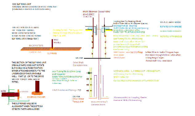
The Male part carries the Slip Rings and rotates with the Turntable Bridge. The Female Part carries the Electrical Contacts in the form of Sprung Brushes and is usually fixed to the underside of the Non-Moving Turntable Well where no Drive Motor is fitted or to the Drive Motor Torque Arm when a Drive Motor is fitted.
The Male Part
This comprises a length of plastic tubing (45mm finished length) – Plastruct TB-24 – that has an o/d of 11/16” (17.35mm) and an i/d of 5/8” (15.9mm).
NOTE: These sizes are not available in the UK and will have to be ordered directly from Plastruct in the US.
The Slip Rings are made from a length of Sticky Backed Copper Tape (About 60mm long and cut 3mm Wide)
4 in No M3 Clearance Holes will be drilled into this INNER Tube at 90 Degree Spacing around the circumference later to take the connecting wires.
The Female Part
This comprises a length of plastic tubing – Plastruct TB-28 – that has an o/d of 7/8” (22.2mm) and an i/d of 3/4” (19.1mm).
NOTE: These sizes are not available in the UK and will have to be ordered directly from Plastruct in the US.
4 in no Holes M3 will be drilled into the OUTER Tube at 10mm spacing to take the electrical Pick-Up Brushes.
The Electrical Pick-Ups are LIMA Sprung Brushes (PS9).
These are mounted inside a ‘Housing Assembly’ made from a length to Plastruct TB-8 tubing – which has an o/d of ¼” (6.35mm) and an i/d of 1/8” (3.2mm)
NOTE: These sizes are not available in the UK and will have to be ordered directly from Plastruct in the US.
M3 Brass Washers are used as Electrical Contacts within the tubes to solder the wires to and make contact with the Brush Spring.
Modifications to Existing Parts
Existing Part 5 – Bearing Block and Part 18 - Bearing will require 4 in No M2 Clearance holes drilling through both, in the same orientation, to carry the wires through.
Part 15 – The Turntable Well will require the center hole opening out to 3/4” to accommodate the DISTANCE PIECE (From TB-20 Tube) and the TB-24 tubing, which will both be attached to Part 18.
The three recesses to take the Drains, one in each part of the Well, require to be drilled out to make ‘through’ holes.
Detailed Work Instructions
- Cut TB-20 Tubing to 5mm long – this will be the DISTANCE RING.
- Cut TB-24 Tubing to 45mm long – this will be the INNER Tube.
- Cut TB-28 Tubing to 45mm long – this will be the OUTER Tube.
- For each tube Identify ‘Top’ and ‘Bottom’. From the ‘Top’ of INNER Tube Mark off at 10mm.
- Draw line around circumference. This is the centerline of the Slip Ring.
- Repeat Step 4 and 5 every 10mm along the length of tube. (Four Centerlines) You should have a 5mm length of tubing below the position of the lower Slip Ring.
- Repeat Steps 4 to 6 for the OUTER Tube.
- Open out the i/d of the first 5mm of TB-24 Tubing at its ‘Top’ end to 16mm (21/32”) or until the DISTANCE RING fits inside it.
- Open out the i/d of TB-28 to 20mm.
- Slide TB-24 (INNER) into TB-28 (OUTER).
- Drill M3 Hole through both tubes at the position of Top Slip Ring ONLY.
- Separate tubes.
- On TB-28 OUTER Tube Drill M3 holes at location of remaining three Slip Ring locations such that all four holes are in line along its length.
- Set up TB-24 INNER Tubing with the previously drilled ‘Through’ Hole on Slip Ring 1 location Rotated 90 Degrees Anti-Clockwise.
- Drill M3 Hole at location of second Slip Ring.
- Repeat Step 14, Rotating 90 Degrees Anti-Clockwise each time for the remaining two Slip Rings. You should end up with 4 M3 holes, each rotated 90 Degrees from its predecessor around the circumference.
- Re-Fit TB-24 into TB-28 and CONFIRM ACCURATE ALIGNMENT of each hole in the OUTER Tube (TB-28) with the corresponding c/l marked on the INNER Tube (TB-24). NOTE: ALL OF THESE MUST ALIGN FOR THE UNIT TO WORK CORRECTLY. THE DATUM IS THE BOTTOM END OF BOTH TUBES.
- Cut suitable lengths of wire, one for each Slip Ring. Strip a 3mm length of insulation from one end of each length of wire and Tin them.
- Cut a 60mm length of Sticky Backed Copper Tape and cut this into 3mm wide lengths. Depending on the width of the original Copper Tape you may have to cut two lengths of 60mm in order to get four 3mm wide by 60mm long pieces.
- Carefully cut and remove a 5mm long section of the Backing Tape from the middle of each length of Copper Tape and remove all adhesive from this section thoroughly.
- Tin across the width on the reverse side – what was the ‘sticky’ side.
- Solder the pre-tinned wires, one to each strip, at the center point of each tape. DO NOT HOLD THE SOLDERING IRON ON TOO LONG OR YOU WILL REMOVE THE ADHESIVE GLUE ON THE REMAINDER OF THE COPPER TAPE.
- When soldered, fit the wire through the M3 hole already drilled in the INNER Tube and feed it out through the ‘Top’ of the tube. Carefully remove one half of the remaining Backing Tape and fit it around and over the centerline marking for the Slip Ring. Press it firmly onto the Tubing ensuring no wrinkles. When one half has been stuck down repeat the process for the second half. There should be a small overlap of tape.
- Cut through both pieces of tape and remove the cut pieces. Both halves should fit snugly together.
- Thoroughly clean the ends of both halves of the tape and Tin them so as to make a continuous electrical connection. DO NOT CREATE A RAISED JOINT HERE. IT MUST BE SMOOTH AND FLAT.
- Repeat Steps 23 to 25 for each Slip Ring.
- Fit the DISTANCE RING to existing Part 18. This is to provide sufficient space for the wires to fit through without fouling the Drive Shaft.
- Check the fit of the INNER Tube (TB-24) over the DISTANCE RING and mark the location of the four wires on the tube. They should be at 90 Degree Spacing around the circumference of the tube.
- It MAY be necessary to cut 4 slots 2mm wide and 5mm deep to take each of the four wires.
- Re-Fit Part 18 to the tube and check alignment. Mark the location of 4 M2 holes to be drilled through Part 18 and Part 5 then remove tube.
- Drill 4 in No M2 holes through both Part 5 and Part 18 to allow the four wires to pass through both parts. It is suggested that both Parts 5 and 18 be fitted together and drilled M2 through both pieces at the same time at the locations as marked out in Step 25.
- Fit all four wires through the M2 holes in Parts 5 and 18 and fit the INNER Tube (TB-24) to existing Part 5.
- The two Feed Wires can now be fitted to the underside of the rails on the Bridge Section.
The Female Part
- Cut suitable lengths of wire to carry the electricity to the Unit. Strip 3mm of insulation from the end of each wire and Tin them.
- Tin 4 of 3mm Brass Washers and solder the end of one wire to each washer. These will form the contact with the Spring Brushes.
- The Spring Brushes are LIMA Part PS9. These are supplied as a Spring and a Graphite/Carbon Brush. One end of the Brush has a reduced diameter to allow the spring to be attached to the Brush. The Spring is 9mm long, the reduced diameter is 2mm long and the actual brush is 3mm long. The Brush fits through the M3 hole previously drilled through the TB-28 Tubing. The Spring is fitted into a ‘Housing’ made from TB-8 Tubing.
The ‘Housing’ comprises a length of plastic tubing (10mm finished length) – Plastruct TB-8 – that has an o/d of 1/4” (6.35mm) and an i/d of 1/8” (3.2mm).
NOTE: These sizes are not available in the UK and will have to be ordered directly from Plastruct in the US.
- Cut 4 off 10mm lengths of tubing. File a concave surface at one end so as to fit to the outside of the OUTER Tube (TB-28), over the hole.
- Cut 4 off 1/8” Plugs from Plastruct 1/8” Plastic Round Rod (PMR-125) 5mm long.
NOTE: These sizes may not be available in the UK and will have to be ordered directly from Plastruct in the US.
- Cut 4 off Lids made from Plastruct 6.4mm Plastic Round Rod (PMR-250) about 1mm thick.
NOTE: These sizes may not be available in the UK and will have to be ordered directly from Plastruct in the US.
- Glue Lid to Plug.
- When dry, drill M2 hole through center of each cap.
- Fit Wire with Brass washer through Cap so that the washer is on the inside of the cap.
- Attach the Spring of the Brush to the Brass Washer and place into tube. You may need to solder the spring to the washer.
- Fit the Cap to the HOUSING Tube. The Brush should protrude into the inside of the OUTER Tube (TB-28) by at least 2mm.
- Pull the cap back sufficiently to withdraw the Brush from inside of the OUTER Tube (TB-28).
- Fit the OUTER (Female) Part onto the INNER (Male) Part. The BOTTOM END of both tubes MUST align together when all Slip Rings and Contacts are aligned.
- The assembly should be a smooth fit. If the thickness of the Copper Strip Slip Rings is preventing a smooth free fit then the i/d of the OUTER Tube (TB-28) (20mm) MAY require opening out slightly more to 21mm to accommodate the INNER Tube (TB-24) of the assembly with its Slip Ring assemblies fitted.
- If the Female Part is to be fitted to the underside of the Turntable Well then 2mm needs to be removed from the length at the TOP of the OUTER Tube (TB-28) to allow for the thickness of the Turntable Well material. REMEMBER – It is the BOTTOM END of both tubes sets the DATUM and MUST align together when all Slip Rings and Contacts are aligned.
- When happy with the fit of both parts Push FULLY home the End Caps on the Brush Housings and glue the complete Housing Assemblies, one covering each hole, to the OUTER Tube (TB-28).
- Connect the appropriate wires to the appropriate supply.